Field-Programmable, Chopper-Stabilized,
Unipolar Hall-Effect Switches
A3250 and
A3251
12
Allegro MicroSystems, Inc.
115 Northeast Cutoff, Box 15036
Worcester, Massachusetts 01615-0036 (508) 853-5000
www.allegromicro.com
Application Information
For additional general application information, visit the Allegro
MicroSystems Web site at www. allegromicro.com.
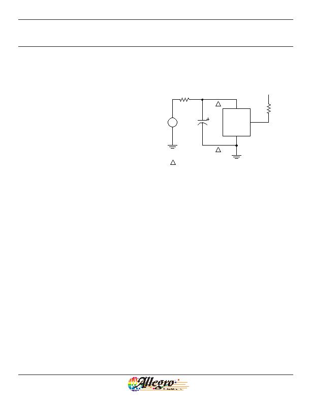
Typical application circuit
Typical Application Circuit
It is strongly recommended that an external ceramic bypass
capacitor, C
BYP
, in the range of 0.01 糉 to 0.1 糉 be connected
between the VCC pin and the supply and GND pin to reduce
both external noise and noise generated by the chopper-stabiliza-
tion technique. (The diagram at the right shows C
BYP
at 0.1 糉.)
C
BYP
should be installed so that the traces that connect it to the
A3250/A3251 are no greater than 5 mm in length. (For program-
ming the device, the capacitor may be further away from the
device, including mounting on the board used for programming
the device.)
The series resistor R
S
, in combination with C
BYP
creates a filter
for EMI pulses. (Additional information on EMC is provided
on the Allegro MicroSystems Web site.) R
S
will have a drop
of approximately 800 mV. This must be taken into consider-
ation when determining the minimum VCC requirement for the
A3250/A3251. The pull-up resistor, R
L
, should be chosen to
limit the current through the output transistor; do not exceed the
maximum continuous output current of the device.
GND
A3250/A3251
VCC
V
Supply
0.1 糉
A
R
L
C
BYP
R
S
100 ?/DIV>
1.2 k?/DIV>
5V
VOUT
A
A
Maximum separation 5 mm
from C
BYP
to device
发布紧急采购,3分钟左右您将得到回复。
相关PDF资料
A3260LUA
IC SW HALL EFFECT BIPO 3-SIP
A3282LLHLT-T
IC SW HALL EFFECT CHOPPER SOT23W
A3340EUA-T
IC SW HALL EFFECT PREC 3-SIP
A3422LKA-T
IC SENSOR DIRECT/DETECT 5-SIP
AAH002-02
SENSORS MAGNETIC FIELD 8SOIC
AD221-00
SENS MAG SW 20G CROS AXIS 8-MSOP
ADH025-00
SENSOR MAG SW 10G CRS AXS 8-MSOP
ADL024-14E
DIGITAL SWITCH 55HZ ULLGA
相关代理商/技术参数
A3251LUATL
制造商:ALLEGRO 制造商全称:Allegro MicroSystems 功能描述:Field-Programmable, Chopper-Stabilized Unipolar Hall-Effect Switches
A325400284-200
制造商: 功能描述: 制造商:undefined 功能描述:
A32550-0009
功能描述:重负荷电源连接器 A32 SOCKET 50mm 50MMSKTCON RoHS:否 制造商:Hirose Connector 系列:PS2 产品类型:Connectors 位置/触点数量: 端接类型:Crimp 触点材料: 触点电镀:Gold 电压额定值: 电流额定值:300 A 附件类型:
A32550-0049
功能描述:重负荷电源连接器 A32 SOCKET 50mm WITH 2 AUX/2 PILOT CONT RoHS:否 制造商:Hirose Connector 系列:PS2 产品类型:Connectors 位置/触点数量: 端接类型:Crimp 触点材料: 触点电镀:Gold 电压额定值: 电流额定值:300 A 附件类型:
A32550-1009
功能描述:重负荷电源连接器 A32 SOCKET 50mm 50MMSKTCON RoHS:否 制造商:Hirose Connector 系列:PS2 产品类型:Connectors 位置/触点数量: 端接类型:Crimp 触点材料: 触点电镀:Gold 电压额定值: 电流额定值:300 A 附件类型:
A32550-1019
功能描述:重负荷电源连接器 A32 SOCKET 50mm WITH 2.5mm AUX CONT RoHS:否 制造商:Hirose Connector 系列:PS2 产品类型:Connectors 位置/触点数量: 端接类型:Crimp 触点材料: 触点电镀:Gold 电压额定值: 电流额定值:300 A 附件类型:
A32550-1049
功能描述:重负荷电源连接器 A32 SOCKET 50mm WITH 2 AUX/2 PILOT CONT RoHS:否 制造商:Hirose Connector 系列:PS2 产品类型:Connectors 位置/触点数量: 端接类型:Crimp 触点材料: 触点电镀:Gold 电压额定值: 电流额定值:300 A 附件类型:
A32570-0009
功能描述:重负荷电源连接器 A32 SOCKET 70mm 70MMSKTCON RoHS:否 制造商:Hirose Connector 系列:PS2 产品类型:Connectors 位置/触点数量: 端接类型:Crimp 触点材料: 触点电镀:Gold 电压额定值: 电流额定值:300 A 附件类型: